Let’s start with the layers on the OSI model. We’re going to go through an overview of each layer, and in the future sections, we’ll go deeper into the layers that are within the scope of this course.
Remember the different layers? Let’s use the mnemonic:
Please Do Not Throw Sausage Pizza Away.
Physical
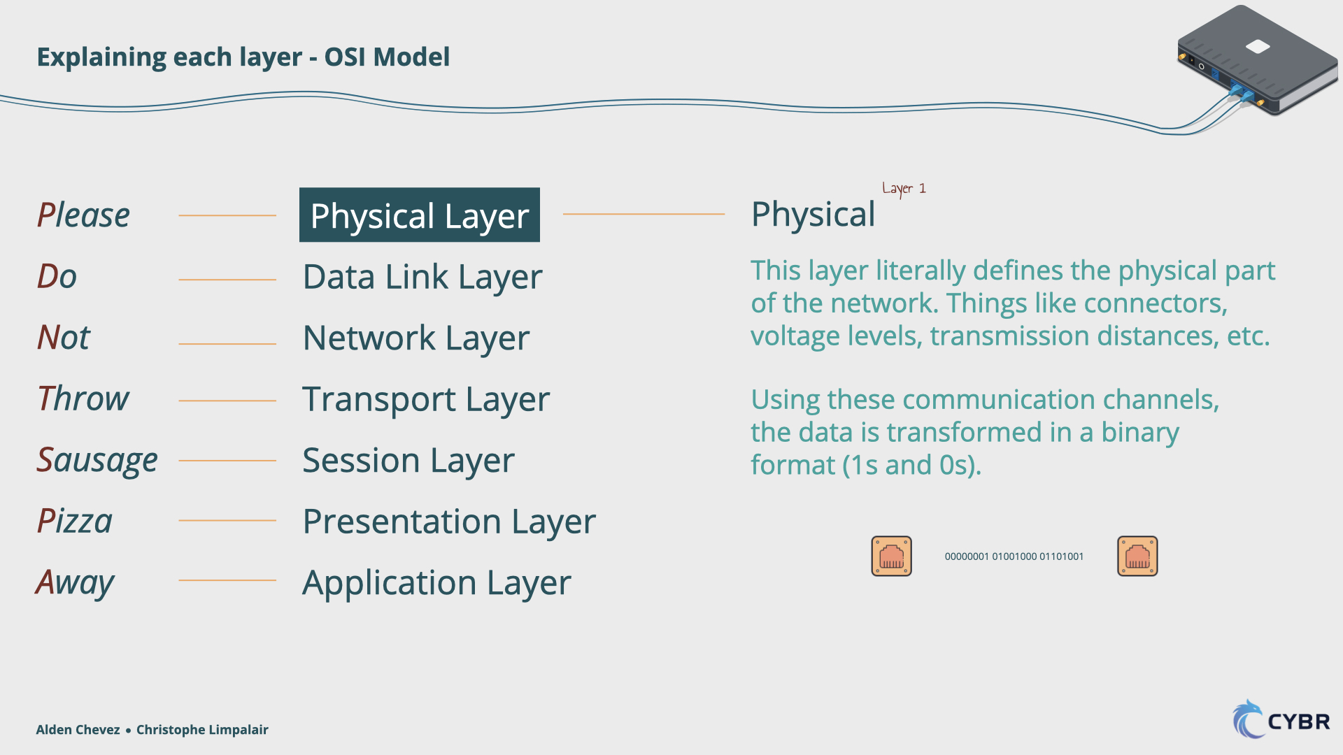
Physical: This layer literally defines the physical parts of the network. Things like connectors, voltage levels, transmission distances, etc. Using these communication channels, the data is transformed in a binary format (1s and 0s). Later in the course, we’ll see exactly how data is transformed into this format and then back into a human-readable format again. It requires a little bit of math, but not too much, so don’t worry!
Data Link

Data Link: Here, data is formatted in a way that it can access the physical layer. Have you ever heard of a computer’s MAC (Media Access Control) address? The MAC address is a Layer 2 address used in Local Area Networks (LAN) – which simply means a network that connects devices within a limited area, like a home, an office, or a school – where a Source MAC address and a Destination MAC address are used to keep track of devices and manage the flow of data.
Network
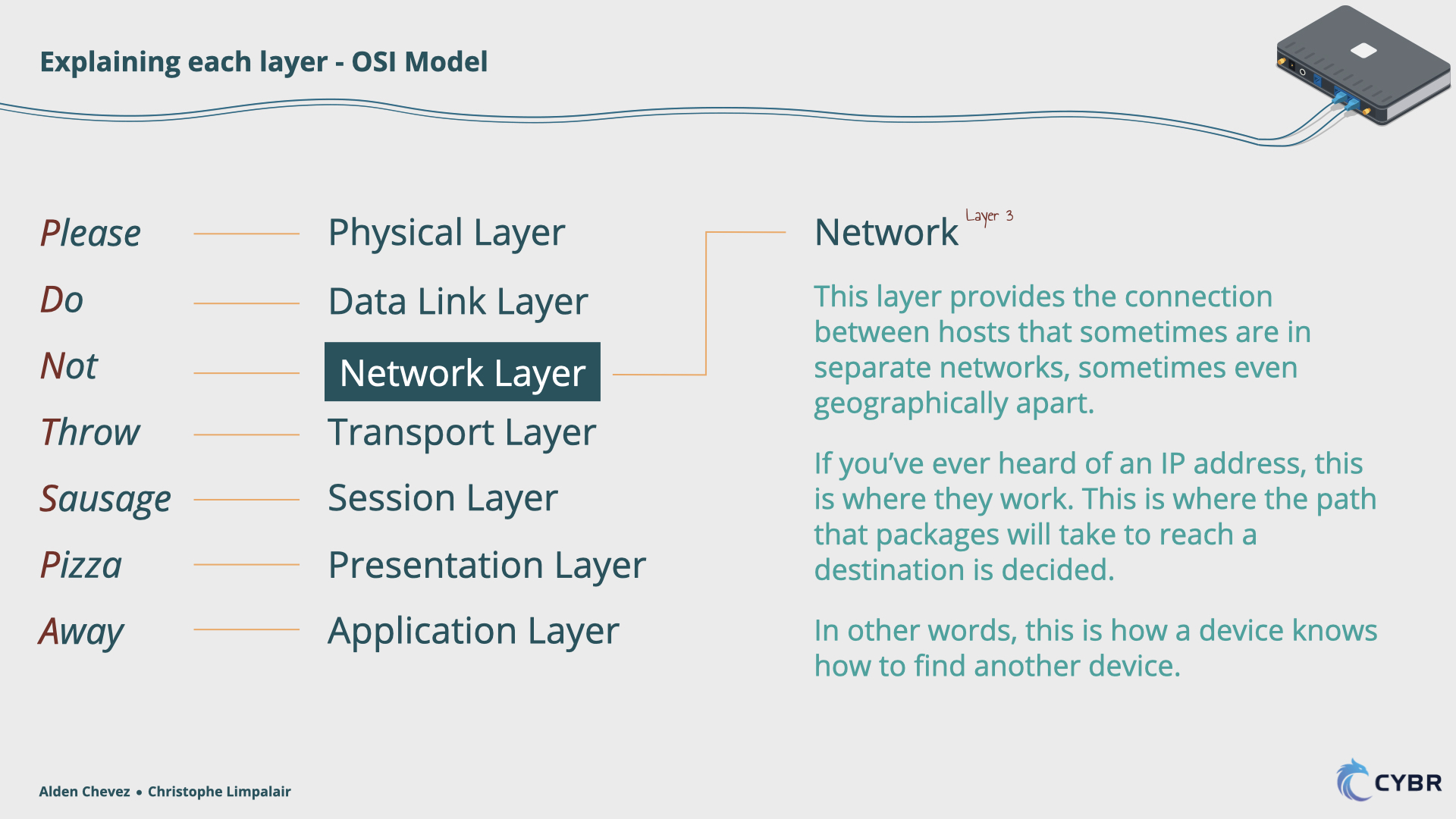
Network: This layer provides the connection between hosts that sometimes are in separate networks, sometimes even geographically apart. If you have ever heard of an IP address, this is where they work. This is where the path that will be used to deliver data is determined, to make sure that the data reaches its destination. In other words, this is how a device knows how to find another device.
Transport
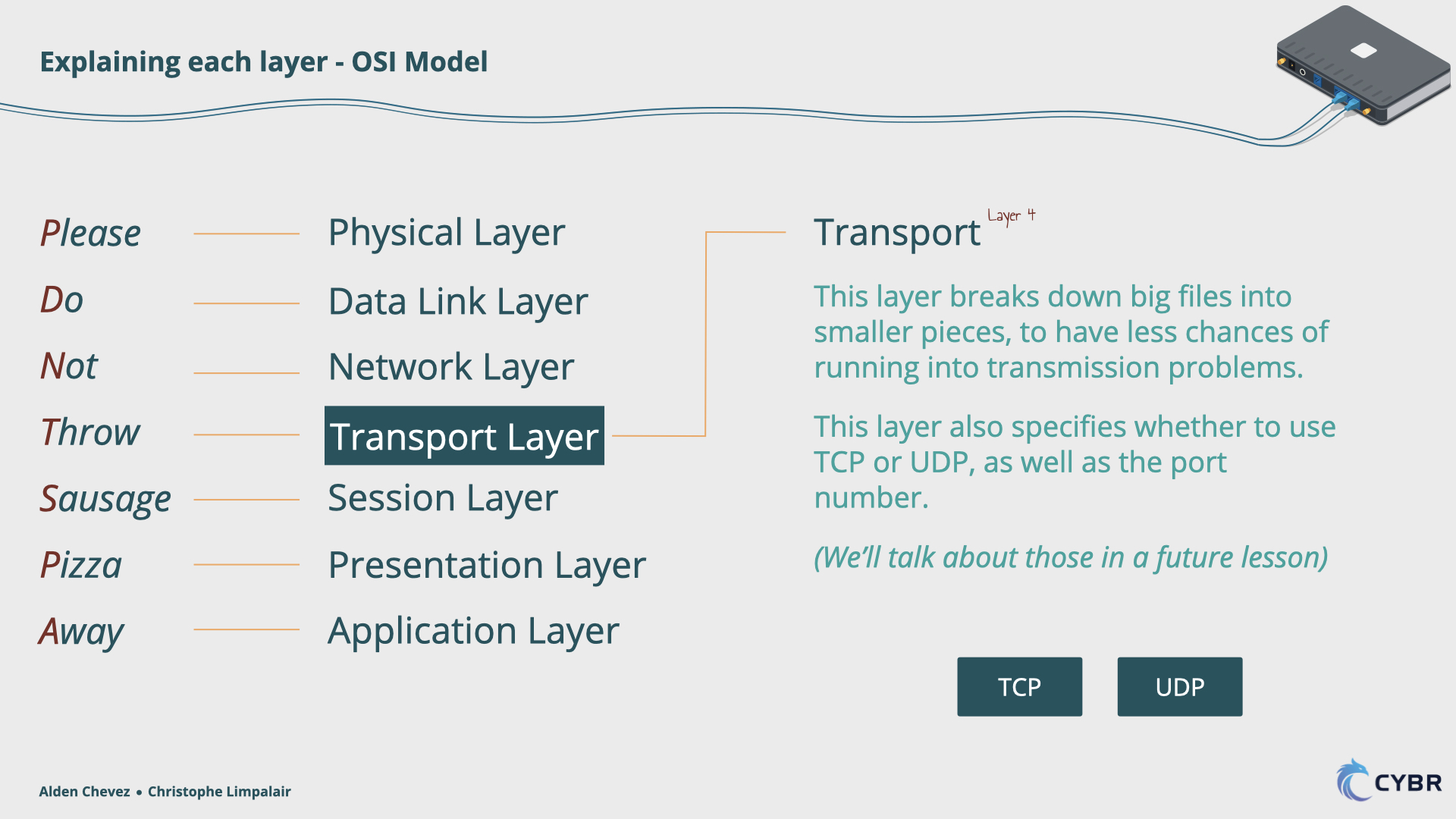
Transport: This layer breaks down big files into smaller pieces, to have fewer chances of running into transmission problems. This layer also specifies if the connection will use TCP or UDP, as well as the port number that will be used. If you don’t know what these are, don’t worry, we will talk about them in the section dedicated to this layer.
Session
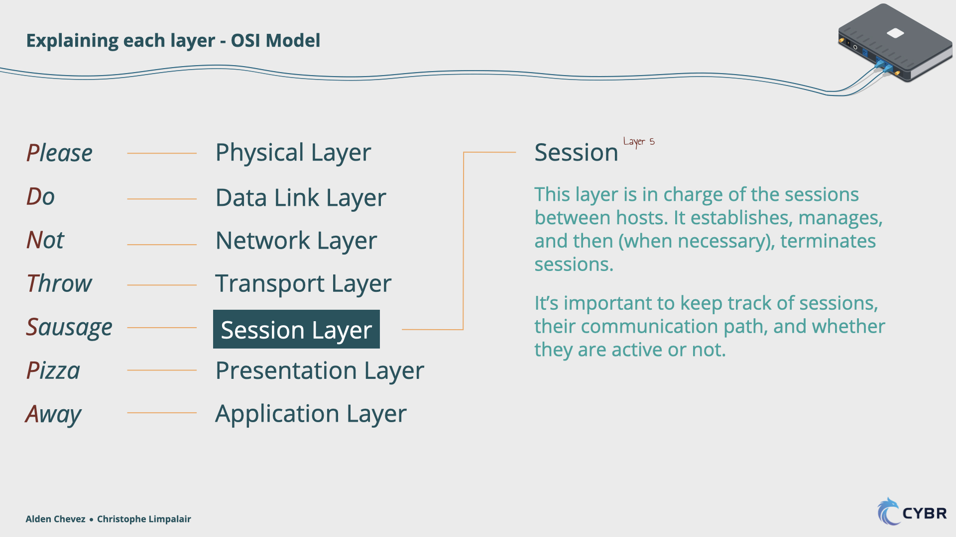
Session: As the name suggests, this layer is in charge of the sessions between hosts. It establishes, manages, and then, when necessary, terminates the sessions. If you have ever played games online, or if you imagine a website with a lot of traffic like a social network (or our video library server), you know that a server can have a lot of users connected at once, and it is very important to keep track of them. You need to keep track of their communication path, if they are active or not, and also, if you have an architecture with redundant servers, you want to know to which specific server the user is connected. Sessions help with all of this.
Presentation
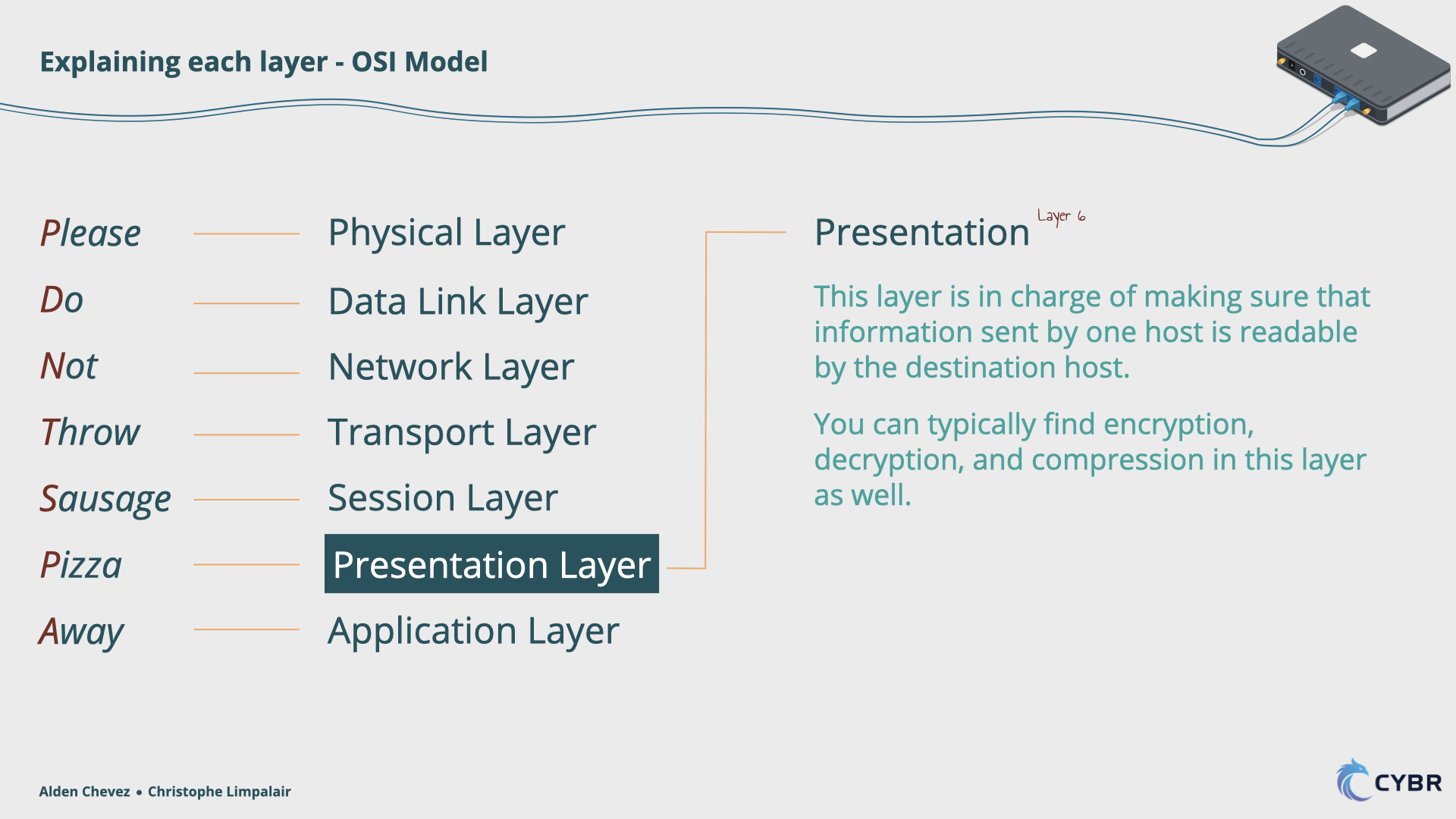
Presentation: This layer is in charge of making sure that the information sent by one host is readable by the destination host. In this layer, you can typically find encryption and decryption.
Application
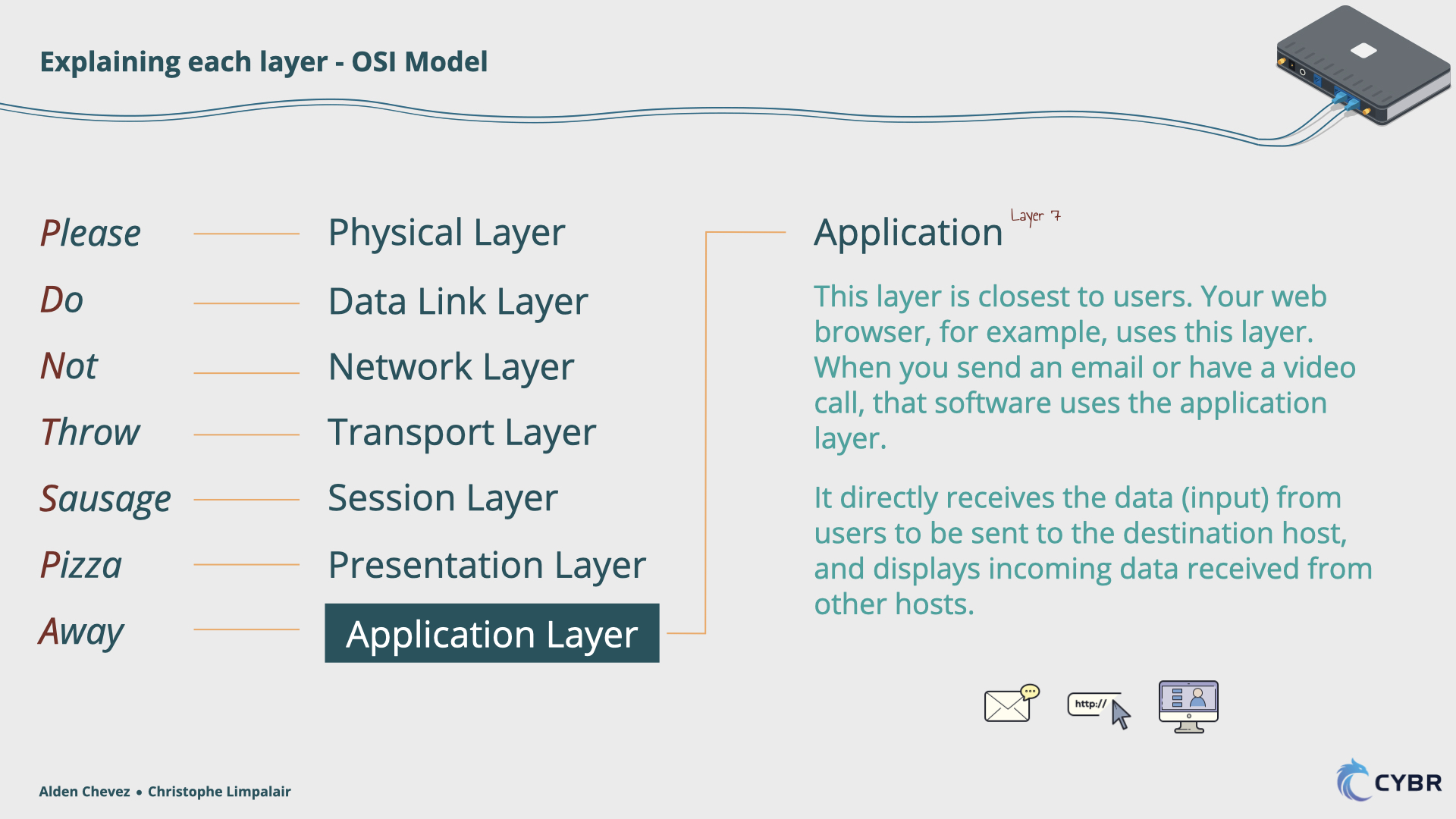
Application: This is the layer that is closest to the users. Your web browser, for example, uses the application layer. When you send an email or have a video call, that software uses the application layer. This layer directly receives the data (or input) from the users to be sent to a destination host and displays the incoming data, received from other hosts. In our example, this is where people search for a video, play it, pause it, etc.
How this compares to the TCP/IP stack
That’s an overview of the layers on the OSI model. Now we will discuss the layers on the TCP/IP model.
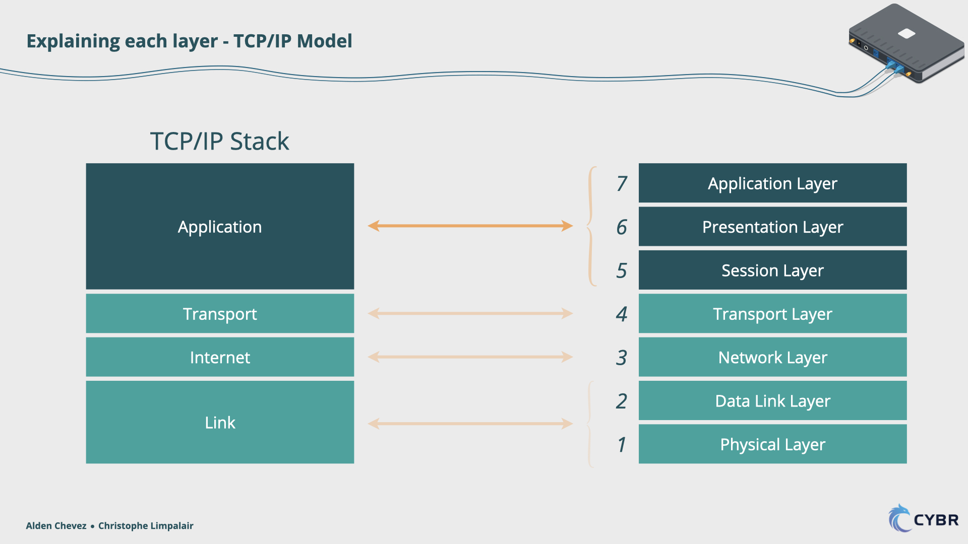
As shown before the layers on this model are:
Link: This layer is the equivalent of the first two layers (Physical and Data Link) of the OSI Model, covering the same aspects.
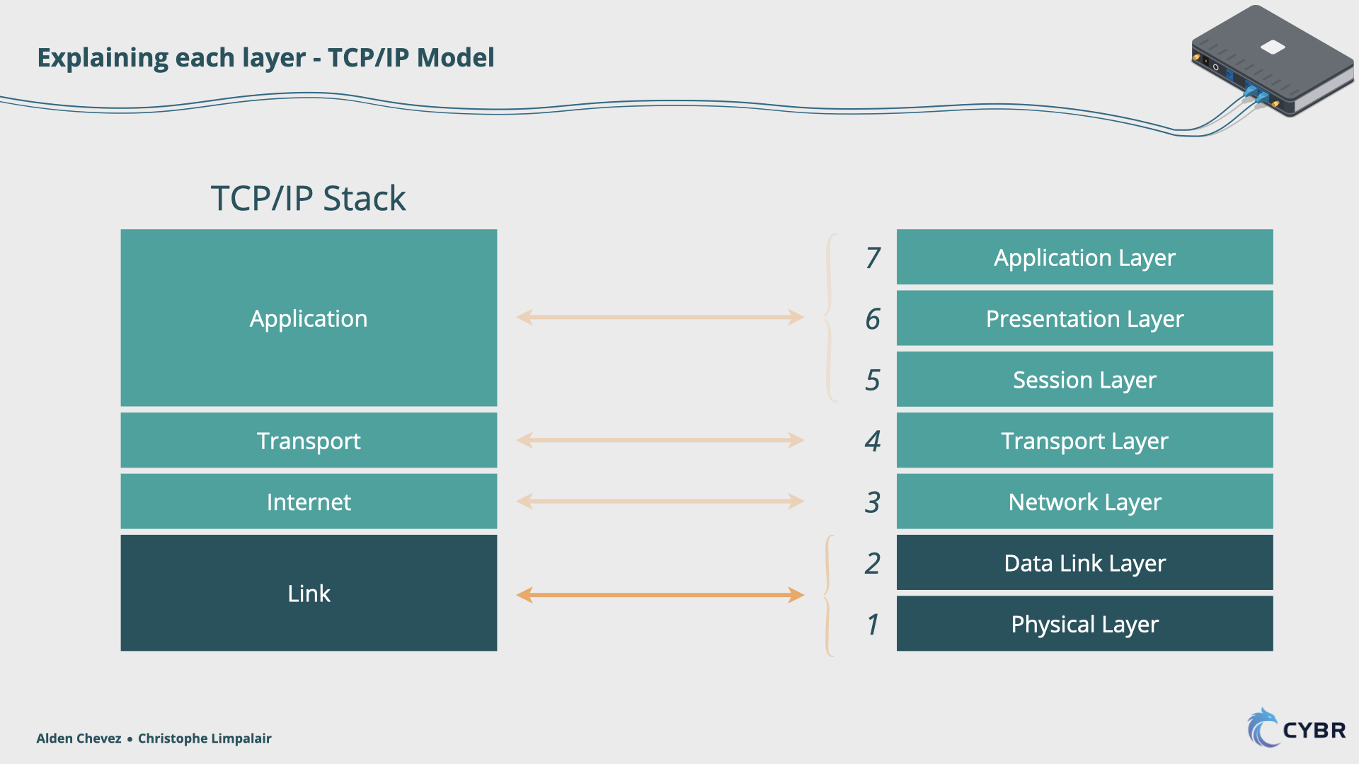
Internet: Aligns with Layer 3 (Network) of the OSI model
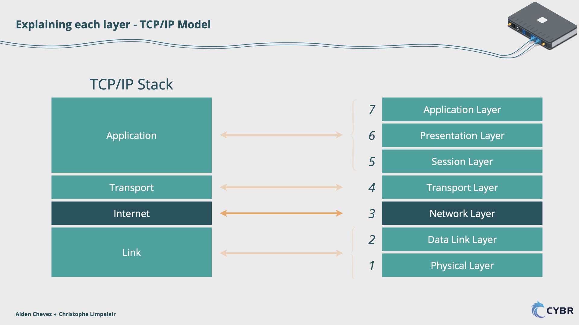
Transport: Aligns with Layer 4 (Transport) of the OSI model

Application: Aligns with Layer 5, 6 and 7 (Session, Presentation, Application) of the OSI model
Now that we understand the function of each Layer, we need to understand how the data is prepared to be sent from one host to another. This process is called Encapsulation.


Responses