Project: Using Cisco Packet Tracer to learn networking

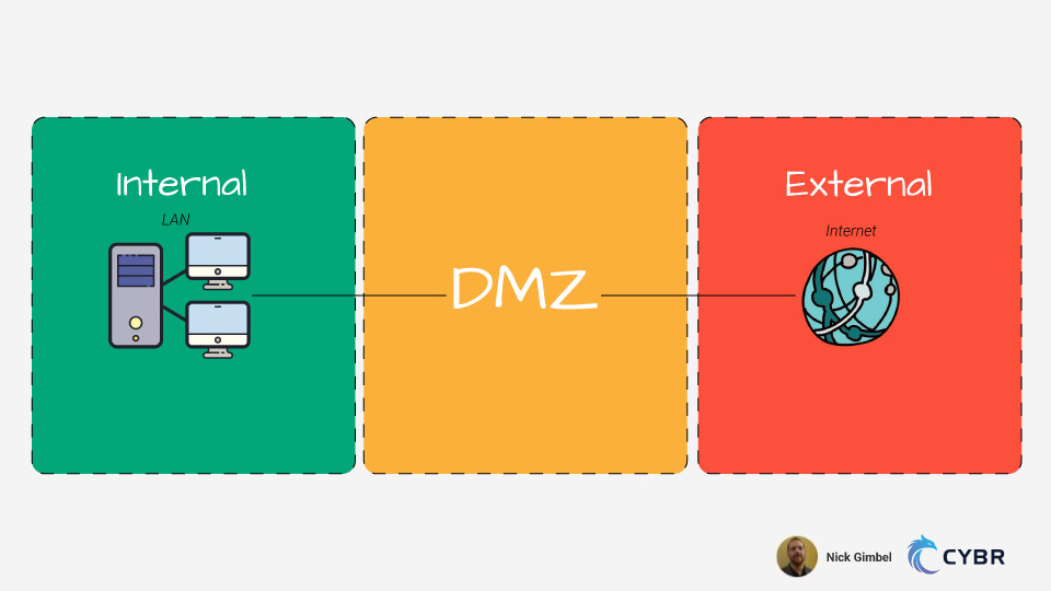
This project was created by Cybr Member, Nick Gimbel. Check out his other related project DMZ and Network Hardening with Packet Tracer.
This tutorial is designed for people who have an introductory knowledge of basic networking. This will expand their understanding of some essential concepts and provide helpful shell tips when dealing with Cisco IOS, Cisco’s Internetwork Operating System, which is a family of network operating systems used by many routers and switches. We will be using Cisco Packet Tracer, which is a popular tool that is important to know in the world of networking.
The main purpose of this tutorial is to help those new to the study of networking and demonstrate how some of the essential protocols come together. This also provides some tips and insight to help as you move towards an intermediate level.
Lab Requirements
- Cisco Packet Tracer (7.3.0)
- Resources from my GitHub
- Enter the NetworkTutorial Folder (feel free to check out my other projects)
- Enter the Basic Practical folder and download contents
- Make a directory for the project and copy downloaded contents in it
To really benefit from this tutorial, have a general understanding of how essential network protocols work. To be more specific for this lab, I’d recommend being familiar with:
- Vlans
- Switchport Modes and Port Security
- Switch trunking
- Router on a stick
- DHCP
- Access-Lists
- Dynamic Routing (Using EIGRP but at minmum try to learn OSPF as well)
- Static Routing
If some of these terms seem foreign to you please research them first and try to understand their basic purpose in a network. An extensive in-depth
knowledge is not required to start configuring and see how these protocols work in action.
If you have trouble understanding them, please reach out in our forums and we will be glad to help!
Lab Setup
How networking labs are approached can significantly increase efficiency and effectiveness. Below is a screenshot of how I would set up the lab in the form of a simple integrated environment that has minimal tabbing and distractions between the instructions and Cisco Packet Tracer. I highly recommend at least trying this approach as, through my experiences I have easily found it to be the best strategy.
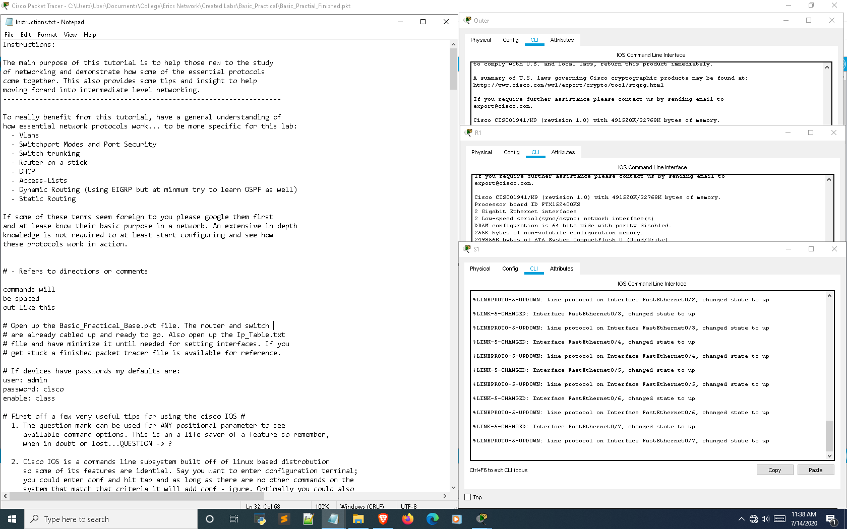
Now that all preliminary measures have been taken to properly set up the lab it’s time to actually get started. You can also refer to the Instructions.txt file for these instructions if you’d prefer downloading them.
Legend
# – Refers to directions or comments
commands will
be spaced
out like this
Getting started with Cisco IOS
Open up the Basic_Practical_Base.pkt file in Cisco Packet Tracer. The router and switch are already cabled up and ready to go. Also open up the Ip_Table.txt file and have it minimized until needed for setting interfaces. If you get stuck, a finished packet tracer file is available for reference (Basic_Practical_Finished.pkt).
If devices have passwords my defaults are:
- user: admin
- password: cisco
- enable: class
First off a few very useful tips for using the cisco IOS
- The question mark can be used for ANY positional parameter to see available command options. This is a a life saver of a feature so remember, when in doubt or lost…QUESTION -> ?
- Cisco IOS is a commands line subsystem built off of Linux so some of its features are identical. Say you want to enter configuration terminal; you could enter conf and hit tab and as long as there are no other commands on the system that match that criteria it will add configure. Optimally you could also just enter
conf tand the system will understand you want to configure terminal. Linux distros can be installed in cisco devices and a Linux subshell can be imported in the Cisco IOS for using commands likegrep. Also, numerous shell movements can be used:- Ctrl + a -> Moves cursor to the beginning of line
- Ctrl + e -> Moves cursor to the end of the line
- Alt + f -> Moves cursor forward a word <-These two did not seem to
- Alt + b -> Moves cursor back a word <-work on Packet Tracer
- If you encounter any protocols or commands your not familiar with, Google: cisco < Protocol Name > or cisco < Command Syntax > Cisco has fantastic documentation that is efficient for picking things up quickly. Still, remember to look into other sources but recommend Cisco as the first.
- To disable most commands just put no before the command. Most of the time this works in an inverse manner. For example, shutdown is to disable an interface and no shutdown is to turn the interface back on.
Step 1: Begin by configuring some basic device environment configurations
This section will set up some essential global commands that affect the entire device as well as the console/Virtual Terminal/Auxilary lines.
When in a situation with multiple routers; config one router and copy over basic running config to the others. The same concept applies to the switches to streamline base configurations
Before starting make sure your labbing setup is similar to what I suggest on the setup tutorial on Cybr. This will create a more efficient lab experience with less interuptions and switching between tabs while focusing on device interaction.
Also some commands might only work on the router and not on the switch and vice versa. Don’t let any error messages get to you keep moving forward compared to a real device packet tracer can also have limited syntax.
To limit confusion I put a (Router Only) label after some of the command explanations on the right side below… this means only the router will accept them when entered.
Basic commands for all devices
| enable | <– Enters global mode which is used to access configuration terminal mode |
| conf t | <– Enters configuration terminal mode |
| hostname [desired hostname] | <– Sets the devices hostname |
| hostname [desire username] privilege 15 secret [desired password] | <– Sets the devices username and password (using physical hardware gives more options of encryption algorithm type |
| no ip domain-lookup | <– Prevents device from preforming dns lookups (leave that to a network server) |
| ip domain-name [domain name of your choice] | <– Assigns the domain name that the device is associated with |
| enable secret [desired password] | <– Assigns MD5 encrypted secret as the password for entering enable mode |
| service password-encryption | <– Encrypts stored passwords |
| secure boot-image | <– Runs integrity check on system image(Router Only) |
| secure boot-config | <– Runs integrity check on startup-configuration(Router Only) |
| banner motd $ Unauthorized Access Is Strictly Prohibited. $ | <– Message of the day banner |
| banner login $ Unauthorized Access Is Strictly Prohibited. $ | <– Login banner(Router Only) |
| no cdp run | <– Disables Cisco Discovery Protocol |
| ip cef | <– enables Cisco Express Forwading(Router Only) |
| line con 0 | <– Enters console line |
| login local | <– Sets login to locally set users |
| logging synch | <– synchronizes the console to prevent interruptions from logs |
| exec-timeout 5 0 | <– Creates a timeout of 5 minutes of inactivity |
| session-limit 1 | <– Limits to a single console session for the device(Router Only) |
| privilege level 15 | <– User logging in need a username with a 15 privilege level assigned |
| transport output ssh | <– Allows the user to only SSH out of the device (NEVER use telnet, Router Only) |
| line vty 0 4 (its line vty 0 15 for switches) | <– Enters Virtual Terminal Lines |
| login local | |
| exec-timeout 5 0 | |
| session-limit 1 | |
| privilege level 15 | |
| transport input ssh | <– Allows only SSH into the device |
| transport output ssh |
| line aux 0 (only on routers) | <– Enters auxillary line |
| login local | |
| exec-timeout 0 1 | <– Creates a timeout of 1 second so even if the password is cracked the threat actor will be logged back out |
| session-limit 1 | |
| privilege level 15 | |
| transport output none | |
| end | |
| wr | <– Write the running configuration |
Type show run in global mode to see what has been done so far. This can be done in other configuration tiers with show commands with…
do show <command>Code language: HTML, XML (xml)This is very helpful with confirming the configurations are correct as well as using show commands.
If you want to enable ssh you also have to enter command:
crypto keys generate rsa This will ask you for a key size. Enter 2048 as the keys bit size.
With username entry always escalate privilege for administrator and ALWAYS use secret over password…its the difference of using MD5 encryption over a weaker standard that takes a few seconds to crack. You can upgrade crypto packages to ensure a stronger SHA encryption.
Also if you have other people managing infrastructure they can be assigned lower privilege levels with parser views so you can control exactly what they are able to access/config/view (though you would have to assign a lower privilege level to the console/vty lines so all users could access.)
no cdp run Can be used to disable cisco discovery protocol, which can be a security liability that reveals device & network information to neighbors. The exception to leaving it on is if a protocol requires it such as voip and should rather be enabled on the corresponding interface rather than globally.
Ip cef enables cisco express forwarding which assists and further improves routing efficiency [works better with next hop rather than exit interface when configuring static routes]. For best results you can actually put both, next hop first followed by the exit interface.
Transport input/output commands determine whether you want any incoming/outgoing ssh sessions with the associated line.
The auxilary line is a security liability if left open. A hacker could connect into a modem and access the aux line through the modem.
What I have configured is straight out NSA’s router security report (Google it if you want a free solid resource). The only thing that could be better is to actually turn off the line with no aux 0, but that is not allowed in packet tracer. Though with the current configuration the hacker would only have one second before they are timed out.
Step 2: Configure device interfaces based off of Ip table and the default gateway on the switch.
conf t
int [interface name] <-- Selects interface
ip add [address] <-- Assigns IP address to selected interface
no shutdown <-- activate interface
endCode language: CSS (css)
On the serial connection between the two routers one end of the cable has a clock on it. The interface this clock is placed on should be set by the command:
clock rate 128000.For the switch use int vlan 40 to assign ip and ip default-gateway to assign the default gateway out of the LAN.
Ignore the f0/0.10-40 interfaces on R1…that will be done later when I go over router on a stick
Step 3: Configure Vlans on Switch
S1
enable
config t
vlan 10 <-- Creates a Vlan
name Office <-- Describes the created Vlan
vlan 20
name Public
vlan 30
name Corporate
vlan 40
name Management
exit
vlan 999
name Black_Hole
endCode language: PHP (php)
Always have a Black hole vlan to assigned unused ports and assign the trunks native vlan to the management vlan. These are both security practices that prevent attacks and it is a common security concept to avoid using defaults. There can be exceptions considering I’m using default port security settings in this lab but that is also because anything more is not needed so the default is acceptable in this case.
Step 4: Configure Switch interfaces
interface range(int ran for short) is incredibly helpful
examples: int ran f0/1-24 or int ran f0/1,f0/3,f0/5,f0/7,etc..
Check all the interfaces that will be used and shutdown any that will not and assign them to the black hole vlan.
config t
show ip int brief <-- Helpful for getting info on port status
int ran f0/8-23,g0/1-2 <-- Selects range of interfaces
shutdown <-- Disables interface
switchport mode access <-- Changes interface status from dynamic to static access mode(dynamic has security flaws)
switchport access vlan 999 <-- Assigns shutdown unused ports to Black Hole VlanCode language: JavaScript (javascript)
Then configure the switchport assignment for the end hosts(f0/1-7).
I recommend selecting the whole range and applying all of the commands except the switcport access vlan. Then select a smaller range per clan and apply that command to prevent error.
int ran f0/1-7
switchport mode access
switchport port-security <-- Assigns the default port security settings
switchport port-security mac-address sticky <-- Binds mac-address to port assignment(default is 1 mac) only allowing certain mac-addrs accessCode language: JavaScript (javascript)
Then select smaller range per vlan on topology and enter:
switchport access vlan [vlan] <-- Assign the vlan in Packet Tracer topology to the selected interfaceCode language: CSS (css)The two port-security commands set the port to only have a single mac-address assigned automatically when activated in the interface…if this is violated the port will automatically shutdown until reset by the administrator (shutdown then a no shutdown will do).
So for example say you had a voip phone daisy-chained into the end host would have to set allowed mac-address to two by using the command switchport port-security maximum 2 or the port would be shut down
Also once the lab is done the end hosts need to be unplugged and replugged back into interfaces so the switch can dynamically learn the mac address or a shutdown followed by a no shutdown on each switchport interface.
Next, the only interface left to configure (int f0/24) going to the router needs to be configured as a trunk.
switchport mode trunk <-- Changes interface status from dynamic to static trunk mode
switchport nonegotiate <-- Refuses any dynamic trunking negotiation protocols (this is a security feature)
switchport trunk allowed vlan 10,20,30,40 <-- Assign what Vlans are allowed to be forwarded through the trunk
switchport trunk native vlan 40 <-- Assigns a native vlanCode language: JavaScript (javascript)
Step 5: Configure R1
To complete our LAN section we need to configure router on a stick.
R1
enable
config t
int G0/0.10 <-- Creates subinterface
encapsulation dot1q 10 <-- Sets encapsulation and defines the associated vlan with the subinterface
ip add 192.168.10.1 255.255.255.0 <-- adds the IP address
int G0/0.20
encapsulation dot1q 20
ip add 192.168.20.1 255.255.255.0
int G0/0.30
encapsulation dot1q 30
ip add 192.168.30.1 255.255.255.0
int G0/0.40
encapsulation dot1q 40 native
ip add 192.168.40.1 255.255.255.248
exit
int G0/0
no shutdown <-- Activates all sub-interfaces (Must be done on main interface!)
endCode language: PHP (php)
Do a show run and show ip int brief to see how the configuration has changed.
If you haven’t already noticed take a second to see how the sub-interfaces, encapsulation assignments, and ip addresses have a direct correlation.
It is time to configure the router as a dhcp server for vlans 10,20,and 30 ….. 40 aka the admin vlan will be statically assigned
Start off by excluding the sub interface address from the pool.
config t
ip dhcp excluded-address 192.168.10.1 <-- Excludes first address in DHCP pool for the router interface to act as a server
ip dhcp excluded-address 192.168.20.1
ip dhcp excluded-address 192.168.30.1Code language: CSS (css)
Now its time to add the DHCP pools.
ip dhcp pool VLAN_10 <-- Assigns a pool for a VLAN where networks can be assigned to dynamically serve IP addresses
default-router 192.168.10.1 <-- Identifies pools DHCP server
network 192.168.10.0 255.255.255.0 <-- Assigns IP DHCP network for selected vlan
exitCode language: CSS (css)
ip dhcp pool VLAN_20
default-router 192.168.20.1
network 192.168.20.0 255.255.255.0
exitCode language: CSS (css)ip dhcp pool VLAN_30
default-router 192.168.30.1
network 192.168.30.0 255.255.255.0
exitCode language: CSS (css)Set all the end hosts to dhcp (config tab except management host which is set statically in ip configuration on desktop tab). Do some ping testing on the command prompt (desktop tab). Confirm dhcp is working by and the vlans can ping each other….
After create an access list to prevent the vlans from accessing the management/admin while maintaining admin access to end hosts.
Access lists use logic and wildcards to determine what networks are allowed and vice versa.
For example, if I use a deny any statement at the beginning of the list and add a permit statement on the next line it wouldn’t matter because an access list is processed like a list from the top down.
My permit statement would never work because all traffic has already been denied before the print statement is accessed. Wilcards are a negation of a subnet mask and and actually tell you how many IP adresses they effect.
For example, if an octet in the subnet mask is 252 the wildcard value would be the inverse (255 – 252 = 3). That being said 252 is the network address of that subnet and 255 is the broadcast… so only 253 and 254 are actually assignable IP addresses.
config t
ip access-list extended MANAGEMENT_FILTER <-- Creates an extended access list
permit ip 192.168.40.0 0.0.0.7 any <-- Allows IP for only the first 7 addresses of vlan 40 specified by the wildcard mask
permit icmp 192.168.40.0 0.0.0.7 any <-- Allows ICMP for only the first seven addresses
deny ip any any <-- Denies IP for any other network
deny icmp any any <-- Denies IP for any other network
exit <-- Exits the acl configuration mode
int g0/0.40 <-- Enters sub-interface
ip access-group MANAGEMENT_FILTER out <-- Assigns access list to interface in a outbound direction
endCode language: PHP (php)
Do some ping tests between vlans to see how the vlan access is altered.
The next access-list prevents anyone but Management PC to access router/switch via ssh.
config t
ip access-list extended KEEP_OUT <-- Creates an extended access list
permit tcp host 192.168.40.3 any eq 22 <-- Permits TCP connections for management host with SSH
exit <-- Exits acl configuration mode
line vty 0 4 <-- selects the 5 Virtual Terminal lines used for SSH connections
access-class KEEP_OUT in <-- Assigns access list in an incoming direction
endCode language: PHP (php)
Try to SSH with one of PCs 1-6 to check if access has been denied
Step 6: Finally its time to do some routing and get some traffic out
First do Eigrp on R1 then Outer.
Getting into routing it is import to understand the general concepts of routing updates and administrative distance (described below).
Administrative distance is an honor system for a router to establish which routes are most trustworthy… it is an extremely important concept to understand for being able to truly understand routing.
Remember do show ip route c which is the command used for determining the locally connected networks that need to be routed and makes the task incredibly simple.
R1
config t
do sh ip route c
router eigrp 99 <-- Creates EIGRP routing process 99
eigrp router-id 1.1.1.1 <-- Assigns logical EIGRP IP address to device, other wise the highest assigned IP is assigned which can be confusing
no auto <-- Prevents EIGRP from auto-sumarizing
passive-interface g0/0 <-- Assigns interface as passive, stopping routing updates from being sent
passive-interface g0/0.10
passive-interface g0/0.20
passive-interface g0/0.30
passive-interface g0/0.40
net 192.168.10.0 0.0.0.255 <-- Assigns network to be added to the routing tables
net 192.168.20.0 0.0.0.255
net 192.168.30.0 0.0.0.255
net 192.168.40.0 0.0.0.7
net 172.16.0.0 0.0.0.3
endCode language: JavaScript (javascript)
next Outer deviceconfig t
router eigrp 99
eigrp router-id 2.2.2.2
no auto
passive-interface lo0
net 172.16.0.0 0.0.0.3
net 209.165.200.1 0.0.0.0
endCode language: CSS (css)Passive-interfaces suppress routing updates which are not needed for your LAN networks or external interface to internet. The fact that they provide routing information can make them a security risk while producing extra traffic that provides no value.
in global non configuration mode type show ip eigrp ? to see options
with viewing your eigrp configurationssh
Step: 7 Finally its time to finish up with static routing
If you’re using packet tracer it does not allow you to shutdown the eigrp process so you should enter the routes default with a lower administrative distance. After testing you will remove them with no command and replace with the same routes with higher administrative distance than eigrp.
So … no shutdown router eigrp 99 is the command needed to remove dynamic routing so static routing can be configured… do this on both routers
R1
static route syntax: ip route <destination network> <destination subnet mask> <next hop or exit interface>
config t
ip route 0.0.0.0 0.0.0.0 172.16.0.1 <-- Creates static route to Outer device
endCode language: CSS (css)
Then on Outer
config t
ip route 192.168.10.0 255.255.255.0 172.16.0.2
ip route 192.168.20.0 255.255.255.0 172.16.0.2 2
ip route 192.168.30.0 255.255.255.0 172.16.0.2 3
ip route 0.0.0.0 0.0.0.0 lo0 4
endCode language: CSS (css)
The list of static routes above cover connection to the three different user lans and a route out to the interet. The order of the routes has a huge effect in the same way as access lists.
Static routes are chosen by administrative distance which is the last number in the command (If not specified like the first entry it assumes the default which is 1).
So based on the list the first the user vlans take priority and any other traffic is caught by the default static route which matches any network on the internet. If I put the default route first this would have caused major issues. There can be only one default route that should be set out towards the internet to ensure connectivity so it will hinder the ability to route traffic from my internal LANs from my private network.
Now if you ping 209.165.200.1 internet gateway through any of PCs 1-6 you have connectivity without any dynamic routing.
Static routes have an AD of 1 by default, EIGRP is an AD of 90. By default static route will have priority over EIGRP due to their lower AD unless set otherwise.
This is not necessary in this lab but helpful in a situation where static and dynamic routing is set up as primary/backup.
Example:
config t
no ip route 0.0.0.0 0.0.0.0 172.16.0.1
ip route 0.0.0.0 0.0.0.0 172.16.0.1 240 <--------- Sets artificially high AD…
causes EIGRP to take overCode language: CSS (css)
Conclusion
That’s it for this lab on using Cisco Packet Tracer to learn Cisco IOS and how to set up basic networks as well as common protocols! Good job and I hope this lab helped!
I’ve also created another project called DMZ and Network Hardening Tutorial with Packet Tracer as well as other types of projects hosted on my GitHub profile!


This project rocks, @ngimb64! Thank you for sharing. I haven’t used Cisco Packet Tracer in a while…you just gave me a great reason to dust it off and try this out.
Way to go Nick! Congratulations, and thank you for sharing this amazing body of work to help others build their Network skills!
Thank you so much Christophe and Shawna!! I appreciate all of your guidance and providing this platform to get additional exposure of my projects.
Hi am yanks the project is grate and i really learn a lot out of it, but i would like download it so that i can try it offline.
Hi Yanks, you can download the project files from GitHub directly, and access those offline: https://github.com/ngimb64/Networking-Tutorials/tree/master/Basic_Practical
So, basically everything seems to work as intended except towards the end when I go to enter “ip route 0.0.0.0 0.0.0.0 lo0 4” i get the error “%Invalid interface type and number.” did I miss a step somewhere?
Let me check in with Nick to see if he’s had a similar issue!
For anyone else who had this issue, I just had to add and no shut the loopback 0 interface. I don’t think that was in the instructions.
conf t
int loopback 0
no shut
end
wr
If you look at step 2 it specifies to configure the interfaces based off the configuration template using the provided IP table. No shutdown is specified on the interface template and the loopback lo0 interface is on the IP table text file so it specifies to enable the loopback.
Awesome, thanks Robert & Nick, and nice job figuring it out