Project: DMZ and Network Hardening Tutorial with Packet Tracer
This tutorial will cover setting up a DMZ architecture as well as some other network security controls.
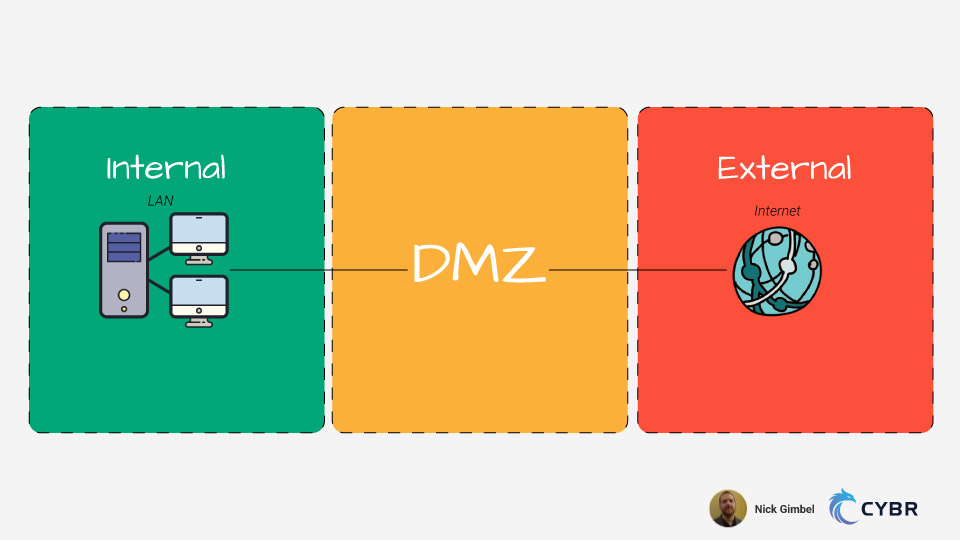
DMZs are demilitarized zones, meaning that they are a subnetwork designed to expose externally-facing services to an untrusted network (usually the open Internet). This is used to protect an organization’s local-area network (LAN) from untrusted traffic. If we visualized it, a DMZ would sit in between the public internet and private networks.
Security controls are most effective when baked into whatever they are being applied to, and network infrastructure is no different. While network automation makes it possible to optimize configurations very quickly, it is more efficient to just get it right initially.
The topology layout consists of three major zones:
- Internal
- DMZ
- External
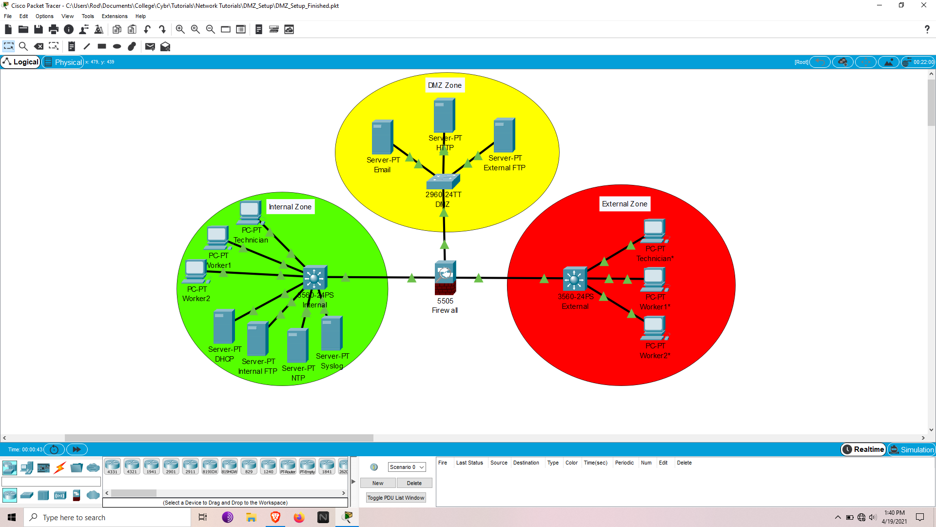
Think of Internal and DMZ together as being our private network. This design strategy is a perfect example of significantly increasing security through network segmentation.
Topics to cover:
- Switchport assignment hardening
- Server Setup
- DCHP Snooping
- Arp Inspection
- Firewall configuration – DMZ setup with static routes
- Login / SSH setup
- Access Control Lists (ACLs)
If some of these terms seem foreign, spend some time researching them and at least know their basic purpose in a network before proceeding.
An extensive in-depth knowledge is not required to at least start configuring and see how these protocols work in action.
Download files for Packet Tracer
All files used in this tutorial can be viewed and downloaded here.
This tutorial includes 2 downloadable pkt files which you can access here:
The first is the base to work from, while the second is so you can see the finished setup and compare with yours.
PKT files can be opened with Packet Tracer by Cisco.
If devices have passwords my defaults are:
- user: admin
- password: cisco
- enable: class
Quick Tips
- The question mark can be used for ANY positional parameter to see available command options
- Ctrl + a -> Moves cursor to the beginning of line
- Ctrl + e -> Moves cursor to the end of the line
Getting started
Base configurations (Environment, Vlans, IP addressing, inter-vlan to static routing) are already set up except the firewall.
These steps are covered in my tutorial called Project: Using Cisco Packet Tracer to learn networking.
Port Security
Lets start out by assigning end hosts to the appropriate vlan and securing physical interfaces.
The vlan design is relatively simple with worker, technician, and separate vlans for various servers.
This helps create segmentation as well as access control when ACLs are applied.
My recommended strategy is to configure the trunk and access ports in separate ranges. Take care of all the uniform commands that apply to all interfaces in that range; then apply interface specific commands like switchport access vlan [vlan #].
An ideal approach:
- Assign unused ports to Black_Hole vlan and shut them off
- Select all access interfaces and assign uniform commands
- Assign interfaces corresponding vlans
On Internal:
conf t
int ran f0/4-19, g0/1-2
switchport access vlan 999
shut
int ran f0/1-23, g0/1-2
switchport mode access
switchport port-security
switchport port-security mac-address sticky
int f0/1
switchport access vlan 20
int ran f0/2-3
switchport access vlan 10
int f0/20
switchport access vlan 30
int f0/21
switchport access vlan 40
int ran f0/22-23
switchport access vlan 50
end
wr
On External:
conf t
int ran f0/4-23, g0/1-2
switchport access vlan 999
shut
int ran f0/1-23, g0/1-2
switchport mode access
switchport port-security
switchport port-security mac-address sticky
int f0/1
switchport access vlan 80
int ran f0/2-3
switchport access vlan 70
end
wr
On DMZ:
conf t
int ran f0/4-23, g0/1-2
switchport access vlan 999
shut
int ran f0/1-23, g0/1-2
switchport mode access
switchport port-security
switchport port-security mac-address sticky
int ran f0/1-3, f0/24
switchport access vlan 50
end
wr
At this point the interfaces should be assigned to their corresponding vlan or shut down.Each interface can only have a single mac-address tied to it or a security violation will shut down the port.
Verify configs:
show run
show ip interface brief
show vlan brief
show port security
Code language: PHP (php)
Internal server setup
To configure servers in Packet Tracer, simply open the server and click on the services tab.
Take notice that all unused services are turned off.
Before configuring any of these services make sure they are toggled on.
DHCP
Now let’s set up DHCP to dynamically assign IP addresses to end hosts.
The DHCP addressing is determined by the IP table. Let’s add a pool for each vlan.
On the DHCP server:
Click on the services tab, go to DHCP, and fill out the following layout:
Pool                Default Gateway         Start IP        Subnet Mask         Max User
Name

serverPool          0.0.0.0                 192.168.30.0    255.255.255.252         0
Worker Pool         192.168.10.1            192.168.10.2    255.255.255.248         2
Technician Pool     192.168.20.1            192.168.20.2    255.255.255.252         1
Code language: CSS (css)
When DHCP is configured through a server, the interface vlans should be assigned a helper IP to the DHCP server.
On Internal:
conf t
int vlan 10
ip helper-address 192.168.30.2
int vlan 20
ip helper-address 192.168.30.2
end
wr
Code language: CSS (css)
At this point DHCP should be configurable on the end hosts. Simply click on the end hosts, click on config tab and select FastEthernet0 or click on desktop tab and ip configuration; then switch from static to DHCP.
For external it will be configured on the L3 switch instead of a server, which is remarkably similar to a router DHCP config.
On External:
conf t
ip dhcp excluded-address 10.0.70.1
ip dhcp excluded-address 10.0.80.1
ip dhcp pool WORKERS
network 10.0.70.0 255.255.255.248
default-router 10.0.70.1
ip dhcp pool TECHNICIAN
network 10.0.80.0 255.255.255.252
default-router 10.0.80.1
end
wr
Code language: CSS (css)
Verify configs
sh run
sh ip dhcp binding
sh ip dhcp pool
Now the external hosts are ready to be assigned IPs.
Internal FTP
First open the FTP server, delete the default username, and use the following layout:
Username        Password        Permission

admin           cisco           RWDNL
user            cisco           RL
Obviously, in an actual scenario, significantly stronger passwords should be used.
For the time being let’s ignore password security and just focus on the protocols.
Verify configs
- Open command prompt on an end host in the Internal zone
- Run command
ftp 192.168.40.2 - Supply user & password (admin, cisco)
- Run
dirto see what’s available - Run
get [name of file]to retrieve a file
NTP & Syslog
NTP & Syslog will be configured on Internal, which will provide logging auditability.
NTP will synchronize system clocks of the network devices in the private network.
Syslog will utilize NTP to facilitate log messages to a server for all devices in the private network.
NTP should be configured first considering that Syslog would be rendered useless without it.
On NTP server:
Enable Authentication
- Key: 1
- Password: cisco
On Syslog server:
Confirm service is activated
On Internal:
Normally timestamps need to be set but that was already taken care of in base configurations for all devices.
There is no need to configure, but here are the commands for reference:
service timestamps log datetime msec
service timestamps debug datetime msec
Now what still needs to be done:
conf t
ntp server 192.168.50.2
ntp authenticate
ntp authentication-key 1 md5 cisco
ntp trusted-key 1
ntp update-calendar
logging 192.168.50.3
logging on
logging userinfo
logging trap
end
wr

Code language: CSS (css)
Verify configs:
show clock
show ntp associations
show ntp status
show logging
External server setup
In the services tab, confirm email service is on, set the domain-name to internal.net, and add the following:
User Password
admin cisco user cisco
Verify configs
- Send an email
HTTP
Confirm service is enabled for http/https.
Verify configs:
- Open a browser on an end host in Internal or External zones and connect to http://172.16.50.4
External FTP
Refer to the Internal FTP configuration above
Verify configs:
- Same method as Internal FTP
Before moving on to configuring the DMZ lets set a few more layer 2 LAN security controls.
DHCP Snooping
This feature monitors and facilitates messages for a DHCP server. It helps identify anomalies in the DHCP DORA (Discover, Offer, Request, Acknowledgement) request process and drops improper requests.
This prevents attackers from modifying DHCP traffic to manipulate it’s dynamic abilities to gain network access.
The only ports that should be trusted are the connections from the switch to the DHCP server and switch to switch connections.
On Internal:
conf t
ip dhcp snooping
ip dhcp snooping vlan 10,20
ip dhcp snooping verify mac-address
int f0/20
ip dhcp snooping trust
ip dhcp snooping limit rate 100
int ran f0/1-19, f0/21-23, g0/1-2
ip dhcp snooping limit rate 20
end
wr
The above configuration not only sets the server port as trusted, but also limits the rate of DHCP traffic allowed through the interfaces.
On External:
conf t
ip dhcp snooping
ip dhcp snooping vlan 70,80
ip dhcp snooping verify mac-address
int ran f0/1-23, g0/1-2
ip dhcp snooping limit rate 20
end
wr
Verify configs:
sh ip dhcp snooping
ARP Inspection
This feature is similar in nature and dependent on DHCP Snooping, but instead monitors ARP traffic.
For those unfamiliar, ARP (Address Resolution Protocol) is used to query the switch for the layer 3 IP address based on the MAC table. Its commonly referred to as a layer 2 to layer 3 address mapping protocol.
Without ARP, DHCP would assign an address but the host would be clueless on how to exit the internal network to the internet. ARP Inspection prevents gratuitous ARP requests, which are manually requested rather than a result of the DHCP DORA process.
This prevents request modification and protects the ARP table from being poisoned. Packets with invalid MAC to IP bindings will be discarded.
On Internal:
conf t
ip arp inspection vlan 10,20
ip arp inspection validate src-mac
end
wr
On External:
conf t
ip arp inspection vlan 70,80
ip arp inspection validate src-mac
end
wr
The rate limit can also be set like DHCP Snooping. By default it’s 15 which is fine for this network.
Verify configs:
sh ip dhcp snooping
DMZ firewall configuration
Now it’s finally time to link the DMZ to the internal zone by configuring the ASA Firewall.
First step is to remove any undesired default settings, then configure the rest.
The model firewall is a Cisco ASA 5505, which operates on a layer 2 vlan setup, so an SVI (Switch Virtual Interface) is required for IP assignment (like a Layer 3 switch).
On Firewall:
conf t
no dhcpd enable inside
no dhcpd address 192.168.1.5-192.168.1.36 inside
no dhcpd auto_config outside
telnet timeout 1
int vlan 1
ip addr 192.168.1.2 255.255.255.252
int vlan 2
nameif dmz
ip addr 172.16.50.1 255.255.255.248
security-level 70
no forward interface vlan 1
int vlan 3
nameif outside
ip addr 209.165.200.2 255.255.255.252
int vlan 4
exit
route inside 192.168.0.0 255.255.0.0 192.168.1.1
route outside 0.0.0.0 0.0.0.0 209.165.200.1
object network inside-net
subnet 192.168.0.0 255.255.0.0
nat (inside,outside) dynamic interface
int e0/0
switchport access vlan 1
no shut
int e0/1
switchport access vlan 2
no shut
int e0/2
switchport access vlan 3
no shut
int e0/3
switchport access vlan 4
shut
int e0/4
switchport access vlan 4
shut
int e0/5
switchport access vlan 4
shut
int e0/6
switchport access vlan 4
shut
int e0/7
switchport access vlan 4
shut
exit
class-map CMAP
match default-inspection-traffic
exit
policy-map PMAP
class CMAP
inspect dns
inspect ftp
inspect http
inspect icmp
exit
service-policy PMAP global
end
write memory
Code language: JavaScript (javascript)
The above configuration removes undesired defaults, configures SVI interfaces (black_hole for unused interfaces), assigns them to a switchport, and disables any unused interfaces (Packet Tracer firewall unfortunately absent of access interface ranges). Then makes a class map that is linked to a policy-map which finally links to the global service-policy.
At this point Internal should be able to communicate any zone while DMZ & External can communicate with each other but are isolated from the Internal zone.
It becomes quite obvious why this is an ideal approach to secure architecture, though it is far from fool proof.
A well crafted block of JavaScript or executables initiated through websites, emails, etc, could still make it through. This can infect the user’s session which can blend their traffic in the user stream to bypass the firewall. Making the attack seem as part of an accepted outgoing connection rather than trying to infiltrate with their own inbound connection.
That’s why end user training is among the most critical aspects of the attack surface. Lack of understanding can result in activity that has potential to bypass layers of security controls.
Verify configs:
sh run
sh ip
sh int ip br
sh nat
sh route
Login/SSH
Normally for larger networks I would recommend utilizing AAA for remote authentication and use local authentication as a backup if the remote server fails.
Considering we’re only going to harden 3 devices, it’s not much of a concern. If connectivity issues occur they still would have to be accessed physically regardless.
On Internal & DMZ:
conf t
username admin privilege 15 secret cisco
enable secret class
login block-for 300 attempts 5 within 120   # <= Login commands unavailable on DMZ L2 switch
login on-success log
login on-failure log
crypto key generate rsa                     # <= hit enter, select biggest key size, hit enter again (Firewall already has key-pair)
line con 0
privilege level 15
login local
exit
line vty 0 15
privilege level 15
login local
end
wr
On Firewall:
conf t
username admin password ciscoasapassword encrypted
enable password class
ssh 192.168.20.2 255.255.255.255 inside
crypto key generate rsa modulus 2048      # <= answer yes when prompted
end
write memory
Code language: JavaScript (javascript)
Verify configs:
sh run
sh login
sh ip ssh
Despite the configuration, SSH still might not work on the ASA in packet tracer. They are a newer feature and still have some buggy issues and are less developed than the routers and switches.
While not available on packet tracer I would recommended disabling telnet and enforcing ssh only.
Access Control Lists (ACL’s)
Now, let’s work on the internal zone as a second layer of protection if the firewall is breached, to isolate internal vlans based on least privilege access control, and for protecting the remote access capabilities of our network device VTY lines.
On Internal:
conf t
ip access-list standard SyslogNTP
deny any
exit
int vlan 50
ip access-group SyslogNTP in
exit
end
ip access-list extended SSH
permit tcp host 192.168.20.2 any eq 22
exit
line vty 0 15
access-class SSH in
wr
Code language: PHP (php)
Verify configs:
sh run
sh access-lists
The above sets the NTP / Syslog Vlan to be inaccessible to end users and SSH login only available to the technician.
Conclusion
We covered a lot in this tutorial, but I hope that you enjoyed following along and setting up your network. At this point, feel free to mess around with ping / traceroute testing in the environment between the different zone combinations to see what works and what doesn’t.
Then, feel free to try and expand this network even further and share what you’ve got with us in the comments below!
This project was created by Cybr Member, Nick Gimbel.


This is an awesome lab and so important to understanding network segmentation and security!
Hi, I was following your tutorial. But, I get some way I stuck, I can’t move. Can you please clarify me if I have to use ssh commands on DMZ (access switch) ?
I am just a student who is trying to learn. thanks
The SSH commands for the DMZ switch would only affect the ability to remotely connect to the switch but should have no effect on the connectivity between the network devices. If your stuck use troubleshooting commands like traceroute to identify where the connectivity is cut in the path. Also Cisco devices have show commands like show ip route .. to display the routing table. show command options can be viewed by the question mark like show ?
Hii Nick this project looks a little tough to catch, can you refer any videos for me to refer, i need your help soon. I am still a beginner at this so, please don’t mind me. Thanks a lot for this content by the way
Hi Nick,
this is great, amazing work.
Do you have a network documentary by any chance?
Hi Mega, we do have a Networking Fundamentals course: https://cybr.com/products/networking-fundamentals/ that’s geared more toward the basics of networking knowledge. Not sure if that’s what you’re looking for!
Hi, may I know the password firewall? I tried to put ‘cisco’ but it was still incorrect.
I don’t understand tha ACL on the multilayer switch (supposed I’ve understood at least this!) . VLAN 50??? It doesn’t exist in internal zone. If i set this ACL on internal VLANs the internal PC cannot communicate any more with anyone, neither on the established connection started fro the internal to the WEB server external. Could you explain me?
Now it’clear. I’ve seen also the pkt (finished) , not only read the tutorial description. I’ve understood VLAN 50 and the ACL.
Thank you for your work